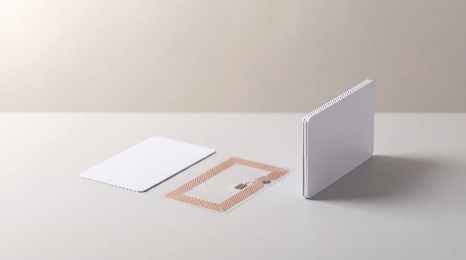
An inlay combines electronics with a physical arrangement that must fit the finished card. Its interfaces matter more to procurement than a cutaway diagram.
October 29, 2026
/
9
min read
An inlay combines electronics with a physical arrangement that must fit the finished card. Its interfaces matter more to procurement than a cutaway diagram.
The inlay is the layer that makes a card contactless: a thin carrier sheet, usually PET, carrying one chip and an antenna, laminated between the printed cores and the clear overlays. A buyer almost never sees it, and does see the consequences. A card reads at arm length on one reader and has to touch another. A batch starts failing after a lanyard slot moved three millimetres.
Those outcomes are set by six properties that are easy to write down and easy to leave out of a purchase order. The Kaway inlay construction record is the single page that holds them: the chip reference, the antenna reference and its outer geometry, the carrier material and thickness, the position of chip and antenna inside the finished outline, the keep-out areas that follow from that position, and one revision number covering the whole combination.
Swipe the diagram sideways to see all of it
An inlay has two effects on a card body: it consumes thickness and it reserves area. Both belong in the specification.
01. The chip reference is the smallest part of the specification
A chip reference identifies the electronics and nothing about the object. MIFARE DESFire EV3 names a chip family and a security architecture, and two inlays carrying it can differ in antenna size, carrier material, chip position and thickness. A purchase order that says DESFire EV3 and stops there has specified about a quarter of what arrives.
Five more lines complete it, each with a different failure mode behind it. The memory variant, because NTAG213, NTAG215 and NTAG216 share an outline and differ in memory. The antenna reference and its outer dimensions, because that decides coupling. The carrier material and thickness, because a 50 micron PET carrier and a paper carrier behave differently under lamination heat. The position of chip and antenna inside the finished outline, measured from the trimmed edge rather than from the sheet. And the keep-out areas, which are a consequence of that position.
Keep the revision number on the combination, not on each part. A supplier can honestly report that the chip has not changed while the antenna layout has, and a record that versions them separately lets a buyer approve a card that was never tested.
02. A chip family is not a construction
Two inlays with the same chip are two different products, and the difference shows up as read range. The antenna harvests the energy the chip runs on. A full ID-1 antenna that runs close to the card edge encloses far more area than the small loop inside a key fob, so it couples more power at the same distance from the same reader. That is why one credential has to touch a wall reader while another is seen from several centimetres away, with identical chips inside.
Tuning is the second difference, and it moves during manufacture. A chip and an antenna form a resonant circuit, and lamination changes it: heat and pressure alter the dielectric around the antenna, so the finished card does not resonate where the bare inlay did. A supplier who quotes a read range measured on the reel has measured something the buyer will never hold. Antenna and read range covers how surrounding metal, the mounting and the reader move that figure again.
ISO/IEC 14443-2 specifies the fields for power and communication between a reader and a proximity card. It describes the finished credential, not an intermediate component.
03. The thickness budget is shared, and the inlay draws first
An inlay spends part of the card thickness budget, and what it spends is not available to the print and the overlays. ISO/IEC 7810 puts the ID-1 nominal thickness at 0.76 mm, the figure every desktop printer, encoder and lock reader is built around. Inside it sit two overlays, two printed cores, the inlay carrier and a chip that is thicker than the carrier it sits on.
Two consequences follow. A thicker carrier or a taller chip module forces thinner cores or thinner overlays, and thin overlays wear through first in a pocket or on a lanyard. And the chip is a local high spot, so the lamination recipe has to absorb it: when it does not, the card shows a visible dimple over the chip, usually after a few weeks rather than on the day it is delivered. Card thickness and lamination covers the five layers and the ways the stack fails.
Thin constructions make the budget tighter, so an inlay qualified at 0.76 mm is not automatically available at 0.50 mm.
Swipe the diagram sideways to see all of it
Each controlled element answers a different question, and only the revision number ties a test result to a product.
04. Keep-out areas are a consequence, not a preference
Keep-out areas are not a design guideline. They are the places where cutting, punching or crushing the card destroys the antenna or the chip, and they move whenever the antenna layout moves. On an ID-1 card the antenna usually runs close to the perimeter, which is exactly where a buyer wants to put a lanyard slot.
Four operations collide with them. A punched slot or a drilled hole cuts the antenna loop if it lands on the run, and a cut loop is a dead card rather than a weak one. Embossing deforms the layers and cracks a chip sitting under the character block. Hot foil and thick spot varnish add local pressure in lamination over the chip area. Laser engraving removes material to a depth that has to stay clear of the carrier.
The supplier states these per construction, which is why an artwork template is issued for a construction rather than for a card size. Custom card artwork covers how keep-out lines reach the print file. Carrying a slot position between two suppliers because it worked before is the most common way a batch arrives dead.
05. An inlay that passes on the reel can still fail as a card
The finished card is the unit of acceptance, so the trial that matters happens after lamination and punching. Three things change between inlay and card: lamination shifts the tuning, trimming fixes the real distance from antenna to edge, and any slot, stripe or emboss applied afterwards alters the card mechanically. An inlay test is a supplier incoming check, not evidence about the credential.
ISO/IEC 10373-6 sets out the test methods for proximity cards and the devices that read them, which is the right vocabulary for an acceptance clause: name the method, not a subjective range. Alongside it sits the application trial on the real installation, which means the actual reader or lock model, the actual mounting surface, the actual firmware version, and cards from the construction being approved.
Record what the trial covered. A card that authenticates on a bench reader at a desk has not been shown to work on a lock mounted on a metal door frame. Card quality plans covers turning that into a test method with an acceptance rule and a named release authority.
06. A change to any line is a new construction until it is re-tested
Treat a change to the construction record as a new product, because that is how it behaves. The common substitutions all look harmless on paper: a chip revision from the same family, a different antenna layout with the same chip, a new carrier supplier at the same declared thickness, a two millimetre shift in chip position to suit a new tool, or a revised lamination recipe. Each can change tuning, keep-out areas, or both.
The clause that makes this workable has four parts. Notice before production rather than with the shipment. Samples built from the new construction, not from old stock. A repeat of the agreed application trial, on the same readers as the original. And a new revision number, with the previous one stated.
That record belongs in the qualification file. Card supplier qualification covers what an approval record names and what it does not cover.
Swipe the diagram sideways to see all of it
The step that gets dropped is the repeated trial, and it is the only one that produces evidence.
07. Buyer checklist
Before approval
Chip reference with the memory variant stated, not just the family name.
Antenna reference and outer dimensions, with the carrier material and thickness.
Position of chip and antenna measured from the trimmed card edge.
Keep-out areas for punching, embossing, foil and laser, stated for this construction.
One revision number covering the whole combination.
Application trial on finished cards, on the real reader or lock model and firmware, recorded against that revision.
Before a reorder
Confirmation in writing that the revision number is unchanged.
Any change classified, re-tested and given a new revision before production starts.
Trial evidence still matching the readers now installed, which may have been upgraded since.
08. Worked example
Illustrative scenario, not a Kaway case study. A buyer has 40,000 approved cards in service on a MIFARE DESFire EV3 construction, with a lanyard slot in the short edge. The supplier proposes a different antenna layout, same chip, to improve yield on a new punching tool.
Treated as a paperwork change, the reorder ships and cards start failing at the doors furthest from their readers, because the new loop encloses less area and the margin that absorbed a metal door frame has gone. Treated as a change of construction, the change is classified as an antenna change, which puts tuning and keep-out areas both in scope. The supplier confirms whether the slot position is still clear of the new antenna run. Samples are built on the new construction and the original trial is repeated at the same doors, including the worst mounting in the estate. The result is recorded against revision two.
The difference is one round of samples and one afternoon of testing, against reissuing credentials to 40,000 holders.
09. Technical references
ISO/IEC 14443-2 specifies the fields for power and bi-directional communication between a reader and a proximity card, which is why compliance is a property of the finished card rather than of the inlay: iso.org/standard/73597.html.
ISO/IEC 10373-6 defines the test methods for proximity cards and the devices that read them, which gives an acceptance clause a named method: iso.org/standard/83862.html.
10. Where Kaway fits
Kaway manufactures in its own plant in Dongguan, China, so the inlay construction, the lamination recipe and the punching tool that sets the keep-out areas sit in one place rather than in three separate plants. Cards have been manufactured at the Dongguan plant since 2007, in a 1,300 m² production plant with 87 people.
Encoding is done at the plant across EM4200, T5577, MIFARE Classic EV1 1K and 4K, MIFARE Ultralight EV1, MIFARE DESFire EV2 and EV3, NTAG213, NTAG215 and NTAG216, ICODE SLIX, and UHF Impinj Monza and Alien H3. Encoding for VingCard, SALTO, dormakaba, Onity and Saflok hotel systems depends on the chip and on the technical requirements, keys and authorisations of the system or the property. Every chip is read-tested individually before shipping, 100 per cent and not sampling, which is a check on the finished card rather than on the inlay.
A sample in your material and chip goes out before any order, and it is the object the construction record should be approved against. Minimum order is 500 units. Standard production is 13 calendar days, 8 calendar days on express and 12 calendar days for wooden cards. Quote requests are answered the same working day. How plastic and RFID cards are manufactured covers the production stages the inlay passes through, and the PVC and recycled PVC range lists the constructions a template is issued for.
Not safely. A chip name fixes the electronics and leaves the antenna geometry, the carrier, the position inside the outline and the keep-out areas open, and those decide read range and where the card can be cut.
Does a read range figure from an inlay datasheet apply to the finished card?
No. Lamination changes the tuning and trimming fixes the real distance from antenna to card edge, so the figure that matters is measured on finished cards, on the reader that will be installed.
Where can a lanyard slot go on an RFID card?
Only where the construction says the antenna does not run. On most ID-1 constructions the antenna follows the perimeter, so the safe area is small and specific to that antenna layout. Ask for it in writing per construction.
Is a chip revision from the same family a change that needs re-testing?
Treat it as one. A revision inside the same family can still move tuning or the chip footprint, and repeating an application trial costs far less than reissuing credentials. Reordering without batch drift covers the other variables that move between batch one and batch two.
About this guide
Published by Kaway Group. The date on this page shows when this guide was last updated. If anything here is out of date, or contradicts what your integrator tells you, tell us and we will correct it.
 HospitalityRoom keys, staff credentials and the pieces around them.
 Retail and loyaltyGift, loyalty and membership cards with variable data.
 Access controlCards and fobs matched to the reader you installed.
 Clubs and associationsOne chip for the turnstile, the locker and the desk.
 Events and festivalsWristbands, badges and lanyards for each edition.